
Tech Articles
Mikuni Carb Installation and Tuning Instructions
Mikuni Carb Kit Installation and Tuning Instructions - Updated 2/4/20
These instructions are primarily for the dual carb kits as used on Volvo 544, 1800, 122, and 140, MGB's, TR4's, etc. where they are used as a direct replacement for SU or ZS carbs. Most of the information is applicable to any dual installation and much of it is also relevant to single, triple and quad installations. For all applications, be sure to read the tuning instructions located after the installation instructions below.
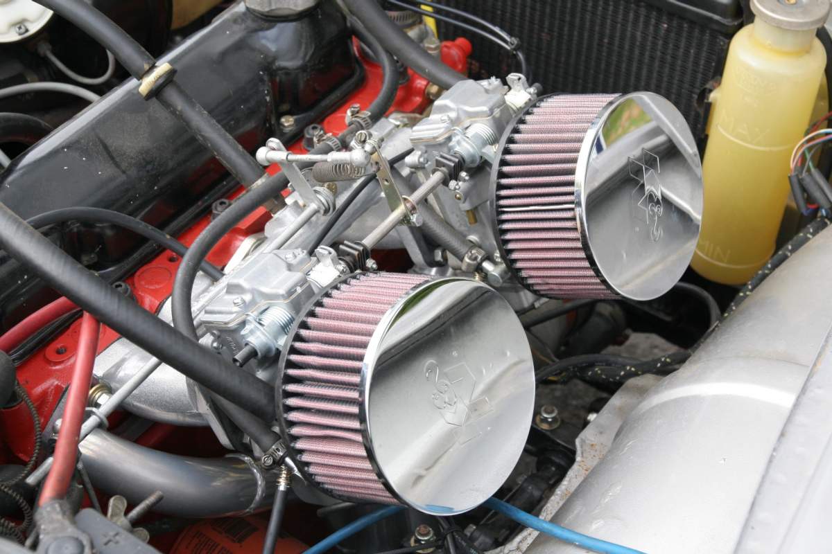
The HSR Mikuni carbs were originally designed to replace SU carbs on Harley Davidson motorcycles but are now widely used to replace SU's on a wide range of cars. The Dual Mikuni Kit contains carbs modified to allow them to be used in tandem to replace dual SU's (or Zenith Strombergs which were themselves an SU replacement) in an automotive application. These modifications include replacement of the original throttle shafts and the installation of a smaller float needle and seat. In addition to the Dual Carb Kit, Single, Tri-carb and Quad carb kits can also be ordered. An installation on a 68 Volvo 1800 is shown below. Note how the linkage provided with the kit hooks up to the orginal SU linkage.
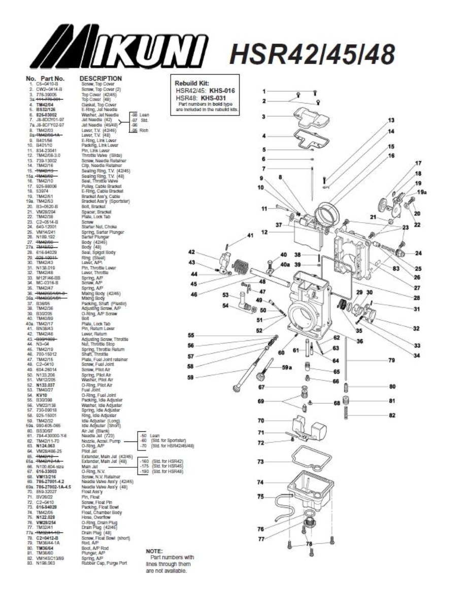
In addition to the intructions found here, instructions are available from Mikuni which refer to tuning the motorcycle applications, though the number sold to replace SU's on cars may now be approaching the number sold for motorcycles. Go to the Mikuni USA website at: http://www.mikuni.com/fs-manuals.html for a downloadable version of their HSR tuning manual, exploded parts view, etc. Basically the HSR 42, 45 and 48 are the same carb except for throat size and stock jetting. Some diagrams from that manual are included below.
The parts included in the dual carb kit are pictured below.
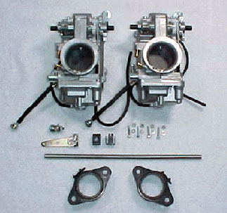
Carb Adapters
The carb adapters are the two black rubber parts pictured above - actually steel plates covered in rubber.
These adapters are used in both automotive and motorcycle applications and are the standard mounts for these carbs. We have used them in extensive testing over the past 10 years, including racing. An significant advantage over more traditional mounting is that they isolate the carbs from engine vibration. A similar type of mount is often used with SU carbs in high performance and competition applications.
.jpg) |
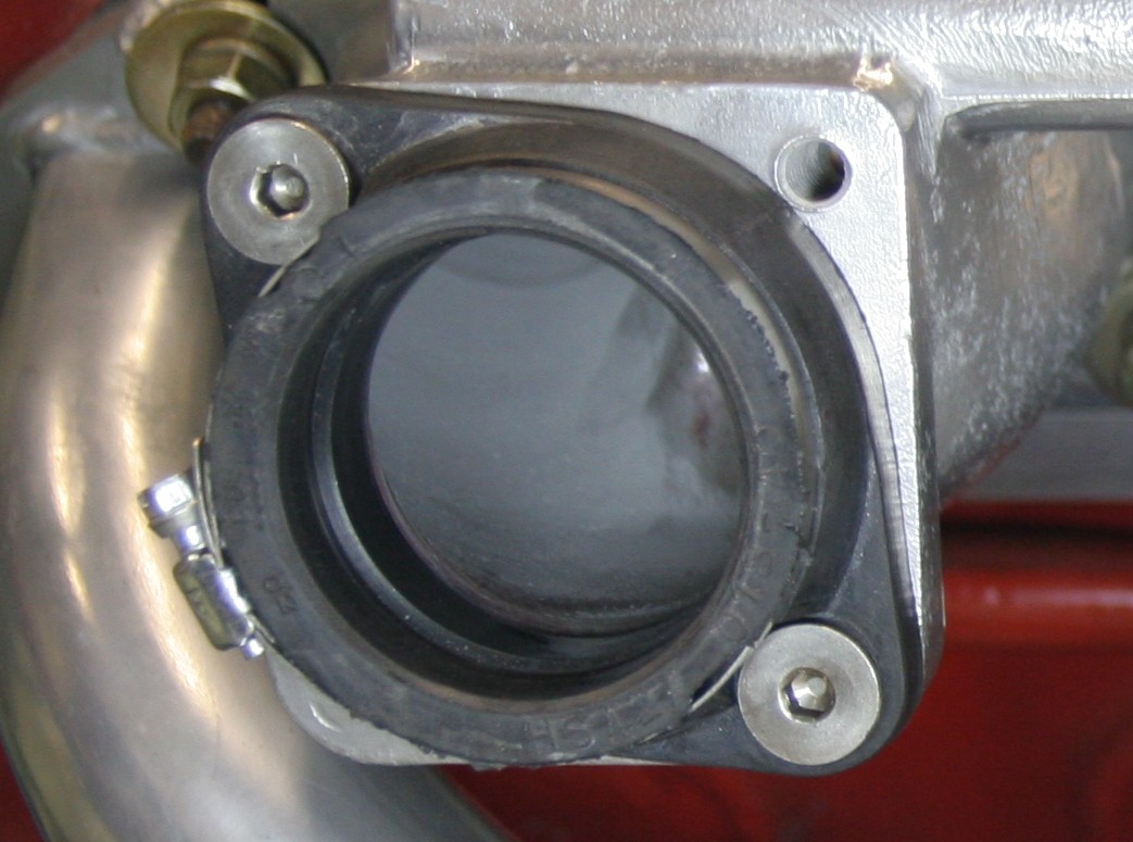 |
Note that the adapters have only two holes for mount studs. Some SU carbs and manifolds use 4 studs, some use two studs. If your manifold has 4 studs, just ignore two of the studs and use the two on each carb that make for the most convenient installation. On some manifolds the studs may be long enough that one or two will have to be removed or they will contact the back of the carb. It is important to prevent this as it can prevent the carbs from seating all the way in mount. It usually makes for a cleaner installation to remove all of the studs and substitute bolts - 5/16 coarse thread in most manifolds. Button head Allen bolts are recommended.
On some of the adapters the holes are spaced fractionally too close together to fit easily on some of the studs. This can easily be taken care of by elongating the holes slightly with a rat tail or chain saw file or small rotary cutter in a die grinder. Remember that there is steel under the rubber so it does not cut easily. On some cars which used smaller carbs, the studs on the manifold are spaced so close together that an additional adapter plate is necessary which we can provide.
To assure a good seal between the carb adapter, the factory heat shield, and the intake manifold, you may want to use the stock type paper gaskets or a gasket sealing/gasket replacement compound. The carbs are secured to the rubber mounts by tightening the hose clamp provided on the mounts. This type of mount not only helps to isolate the carbs from engine vibration - a significant problem with SU and ZS carbs - but also makes it very easy to remove the carbs when needed. Just make sure that the carbs are fully seated and mounted in line with each other before tightening.
Throttle Linkage - Our carb kits come with linkage parts designed to facilitate hooking up to each car's existing linkage. In some cases this is really a simple process and requires no modifications to the existing linkage. This is the case in the Volvo applications shown in photos below, as well as most applications replacing SU carbs, or where a throttle cable is used. In other cases some modifications are needed. The Mikuni throttle shafts rotate in the same direction to open the throttle as SU carbs do minimizing any changes. Zenith Stromberg carb throttle shafts may rotate in the opposite direction to open. When replacing these carbs using rod type linkage some additional modication to the linkage is required to change the direction of rotation. This can be as simple as rotating a lever arm on a throttle linkage shaft so that it will push a connecting link across instead of down or flipping a bell crank so that it pushes a lever arm in the opposite direction. Additional information on how to do this in the TR4, TR6 and GT6 is being added at the end of this section.
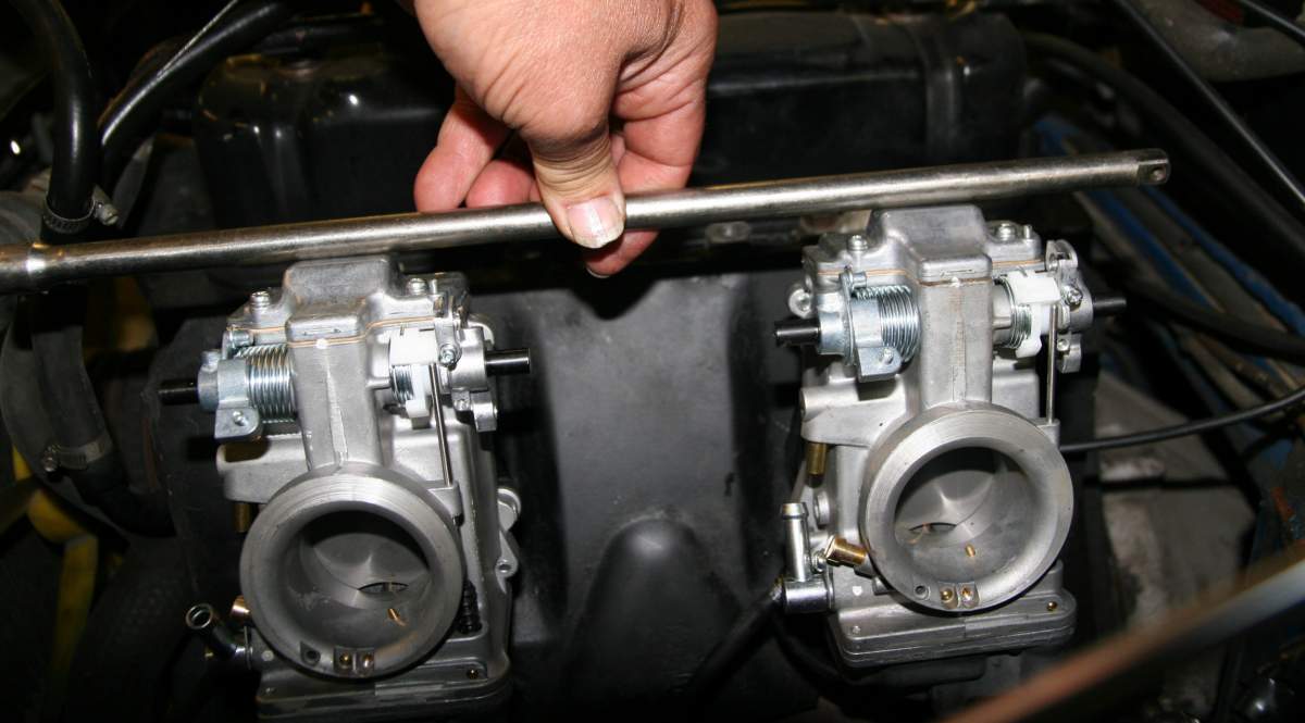
The carbs in the dual and triple carb kits have been modified with longer throttle shafts that extend out each side of the carb. This extension is used to connect to an intermediary shaft that spans the distance between and connects the carbs. The intermediary shaft included is normally cut long, to be sure that it will be long enough for the various applications with different carb spacing. It will normally have to be cut for each application. A simple hack saw will do the job. Just sand or file the end smooth. When measuring the length to cut the intermediary shaft its important that the carbs are fully seated in their mounts and are rotated so that they are parallel to each other. This assures that the shafts will line up and that the intermediate shaft will be the right length. An easy method to make sure that they are parallel is to put a straight edge across the tops of both carbs as in the photo below:


Two shaft couplers are included with the kit. Slide one over each end of the of the stub shafts on the ends of the carbs facing each other. ( In some instances the ends are rough and need to be smoothed with a file in order for the couplers to slide on.) If using a lever arm to connect to the throttle linkage, slide it onto the connecting shaft at this time. Place the shortened connecting shaft between the end of the throttle shaft stubs and slide the couplers so that they are half on the throttle shaft stubs and half on the connecting shaft. Next, insert the small screws into the couplers and tighten each one to firmly attach the couplers to each shaft. Make sure that the connectors are tight enough and adjusted properly so that the shafts do not slip and that both carbs will open all the way equally. For the linkage to work smoothly the carbs have to be mounted parallel to each other.
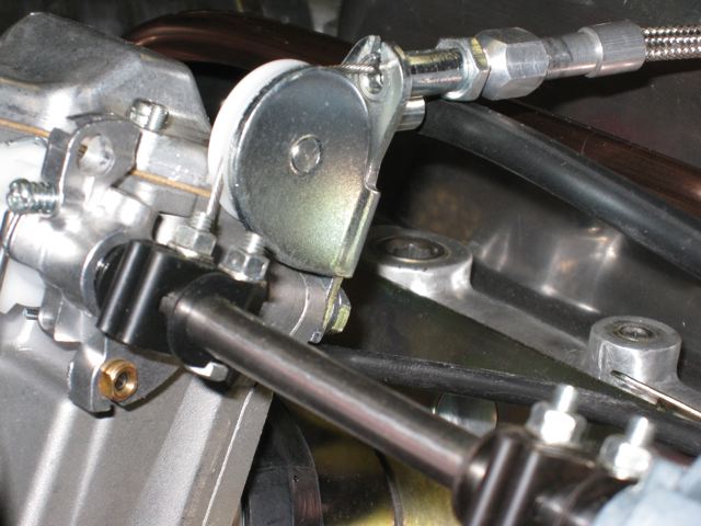
When using stock SU linkage on a Volvo B18/B20 or other engine with rod and lever type throttle linkage, rotate the linkage arm on the connecting shaft until it lines up with the linkage arm that was used to couple to the SU carb linkage. There should be a ball end stud in the kit. This should be attached to the hole in the lever arm farthest from the connecting shaft end. The ball socket end of the arm on your original linkage should fit over the end of this ball stud. When the linkage is attached, but still loose, you can work on making sure that the carbs are in proper synchronization ( they start to open and finish opening at the same time ) and that both fully open and close. Also, be sure that linkage is setup so that at wide open throttle - throttle pedal to the floor - it is not putting pressure on the carbs to push them out of their mounts. This is adjusted by rotating the throttle arm on the intermediate shaft and/or adjusting the length of the linkage rod between the two lever arms as shown in the photo below. It is strongly recommended that an additional throttle return spring be attached to assure that the throttle slides return all the way to the idle speed setting when the throttle is closed.
The photo below shows the stock SU lever type linkage on a Volvo 140 attached to lever arm on the shaft between the 2 carbs. Note the throttle return spring recommended to assure that the throttle plates completely return to their resting position.
As an alternative to connecting the throttle cabe or linkage rod to the lever on the intermediate shaft, a throttle cable can be attached directly to one of the carbs using an available adapter bracket as in single carb applications.
Choke.
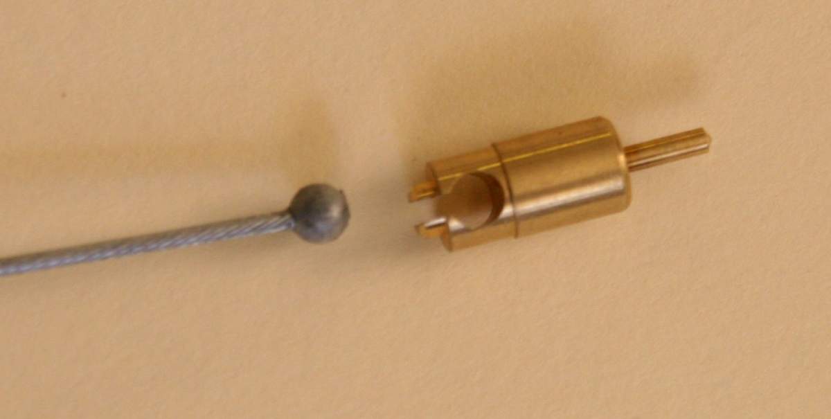
Choke hook-up is simple and will normally use the car's stock choke cable, either dual or single, with a modification to put the right size "ball" fitting on the end. However, some customers have found it easier to replace the stock cables with brake cables from a bicycle shop. If your stock cables are not long enough there is an easy and inexpensive way to extend them. See installation details below.
.jpg)
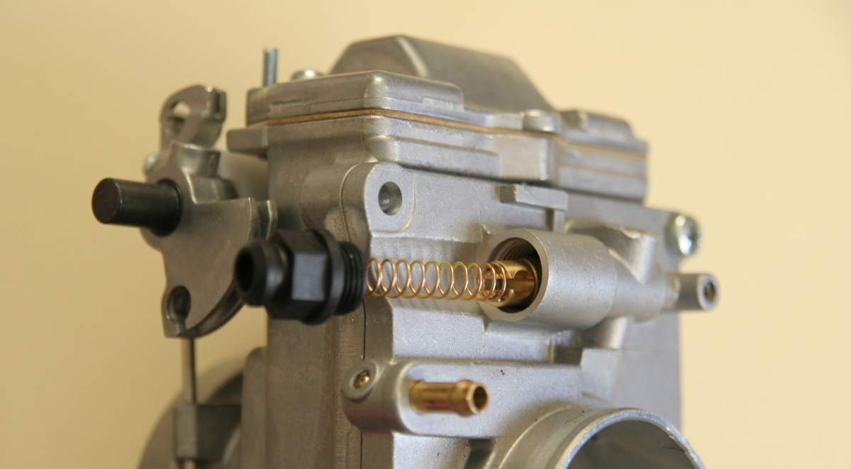
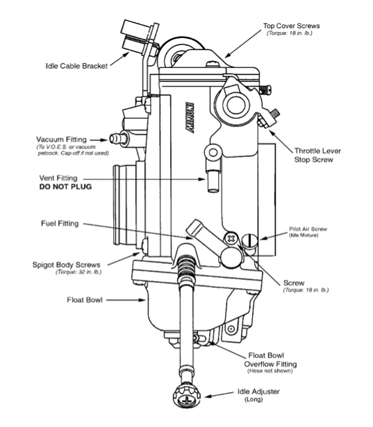
On the back of the carb there is a black fitting in the shape of a hex nut with a small hole in the center. ( Some carbs may be delivered with a short choke cable attached through this hole. ) In either case, unscrew this fitting. There is a spring behind it that will cause the fitting to pop out when it is unscrewed. Under the spring is a brass plunger with a slot in the top that looks like a screw head. This is the cold start plunger. Pulling it outwards with the choke cable opens a passage which allows more fuel to flow into the carb. If it does not fall out when tapping the carb, insert a small screwdriver into the slot and it should pop out when turned.
If using the original cables, all that is usually needed to adapt the standard choke cables to the carb is the addition of a small ball on the end of your cable sized to fit into this slot. Where to put the ball on the cable is determined by the length from ball to sheath that you will need to get sufficient movement. If both ends of the cable are free you can first attach the ball, then cut or adjust the other end of the cable to length. A "ball" can be brazed onto the end of the cable or can be crimped on. Most hardware stores carry a selection of cable ends that can be crimped on.
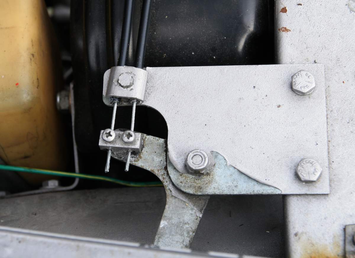
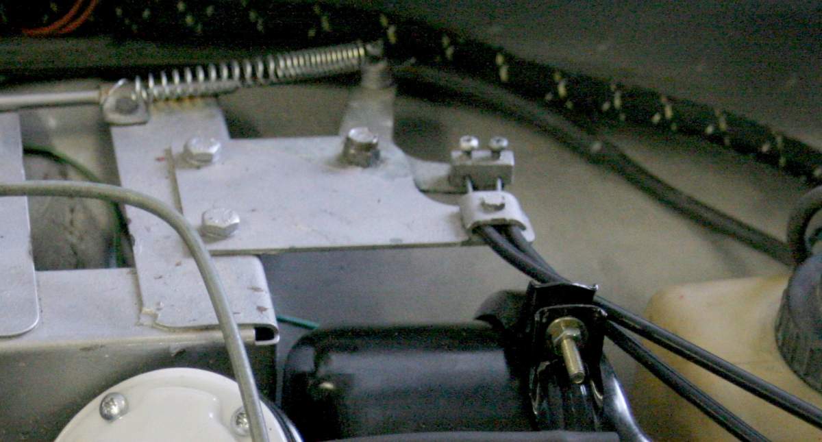
Sometimes it is easier to replace the two original carb choke cables, especially on cars that use a bellcrank arrangement to go from a single cable coming from the dash to two cables at the carbs, as on the '68 Volvo 1800 shown in the two photos below.
 |
 |
 |
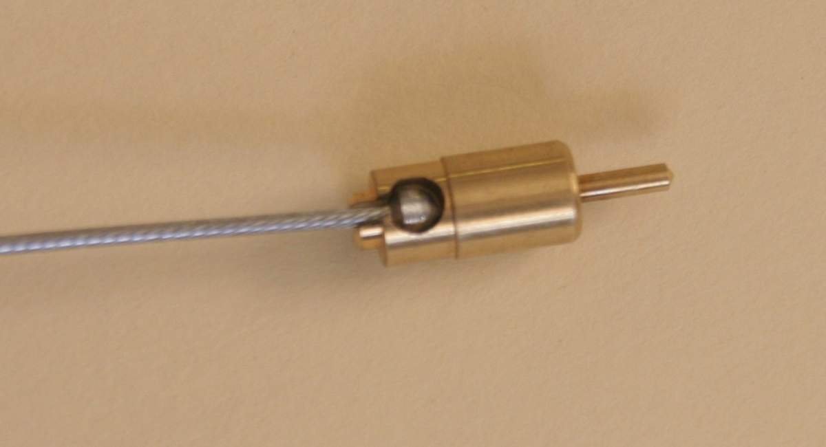 |
If you need new cables and sheaths, try a bicycle store and use two brake cables. They are inexpensive and come with a ball on the end that can be modified ( ground down ) to fit into the carb choke "plunger"hole, as shown in the photos above.
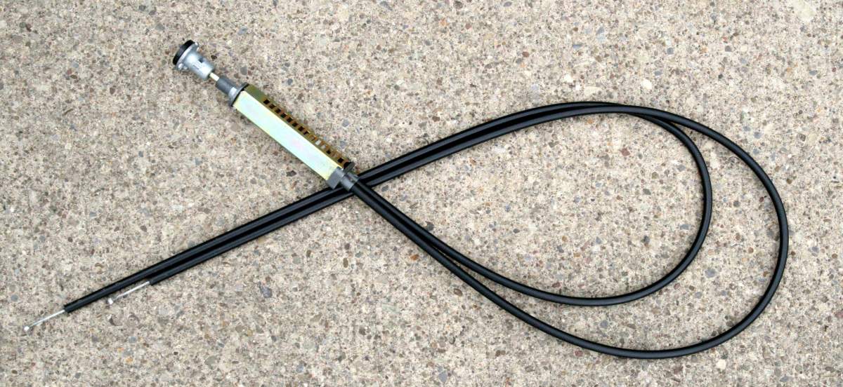
If you have a problem with the choke cable contact us and we can usually provide a cable for use in your application. The photo above shows the dual choke cable from a Datsun 510 that I used in an MGB installation.
Below is our cable splitter with choke cable. See separate installation instructions.
.jpg)
.jpg) |
.jpg) |
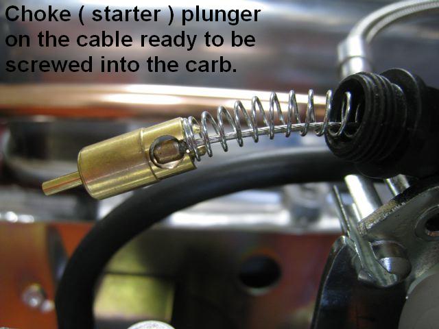
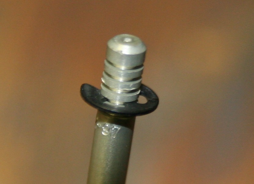
Choke Bracket Installation - The bracket bolts to the front carb by removing the top two screws in the back of the carb and replacing them with the longer screws provided with the bracket system and are used to secure the bracket to the carb. Your choke cable is inserted in the hole in the stud at the top of the arm and clamped in place by tighening the nut. Supplied cables with sheaths for each carb are inserted in the choke plunger as illustrated in the photos showing the plunger above, and then routed to the holes in the stud at the bottom of the arm - clamped in place by tighteneing the nuts to hold the cables in place. Besure that there is some slack in the cable so that the choke will remain closed unless the cable is pulled.
Float Bowl Vent tube.
There is a vent tube coming out of the bottom of the float bowl. Although it is designed as a vent, it can also discharge excess fuel if the level of fuel in the bowl is too high due to excess fuel pressure or a stuck float needle. The tube end should be positioned so that it can drain safely onto the ground if the float sticks. It should be pointed away from the header as there are circumstances in which it could leak raw fuel if the float sticks, etc. Discharges can be reduced by bringing the tube up to the level of the top of the float bowl. Getting significant fuel out of the vent tube is usually an indication that the fuel pressue is too high and is driving the needle off the seat. If this happens you should check to be sure that the carb has the 2.3 size needle and seat designed for automotive applications and that the fuel pressue is less than 3 lbs. In some cases we have had to go as low as 2 lbs. fuel pressure. Another cause for fuel discharge is particles in the fuel that prevent the float needle from closing all the way.
Vacuum Fittings
There are two fittings for vacuum takeoff on the back of the carb. The lower one normally comes
with a black rubber cover on it and can be used to connect your evaporative emission system to the carb. If the top one is not going to be used for a vacuum feed to a vacuum advance distributor, etc. it should also be covered, sealed off. If you do not have an appropriate cap, this can be done with a piece of hose or tube with one end blocked or, as an alternative, you can attach a 1/8" I.D. hose from the fitting on one carb to the fitting on the other. ( In some applications it is preferable to take the vacuum signal for a vacuum advance distributor from the intake manifold rather than the carbs. ) Note that some cars for US markets from the late 60's through mid 70's had vacuum retard distributors for emissions purposes and this was one of the reasons that european models usually had better performance. If your distributor is vacuum retard, we suggest not connecting the vacuum line to it. Or better yet, change to a vacuum advance distributor which will significantly increase performance and fuel mileage. The 123ignition electronic distributors are recommended as the best upgrade option with vacuum advance and either programable or selectable advance curves.
Fuel Lines
Many fuel line setups for SU carbs had a single fuel line that feeds the front carb, and another line from the front carb to the rear carb. If that is your car's setup, in order to hook up the Mikunis you will have to put a "T" fitting in the fuel line, with relatively equal lengths of hose going to each carb. Suitable plastic or brass "T" fittings can be found at most automotive supply and plumbing stores. When installing the fuel lines be very careful not that you do not damage the inside of the fuel lines when installing them on metal fittings as this has lead several customers to wonder why their float needle and seat were sticking - the answer - small pieces of rubber left in the fuel line on the carb side of the fuel filter. I also recommend against installing a fuel rail above the carbs. It looks neat, but the volume of fuel in the rail, above the carbs, will put costant pressure on the float bowl needle and seat and could result in extra fuel leaking into the float bowl while the car is sitting.
Fuel Pressure
These carbs normally come from the factory with float bowl needles and seats ( size 4.0 ) setup for low fuel pressure - motorcycles use gravity feed from the fuel tank above the motor. From early 2007 on, all of our kits have been supplied with a smaller needle and seat (size 2.3 ). However, as in all carb applications, fuel pressure should limited and should not exceed 3 - 4 PSI. If you have a fuel pressure regulator just turn down the pressure to 2 - 3 lbs. If you are getting fuel coming out of the float bowl vent hose ( the black hose at the bottom of the carb ) the fuel level in the bowl is too high, probably because the needle and seat is not closing as it should. This is usually because the fuel pressure is too high or a foreign object is preventing it from closing completely. Often the object is a piece of rubber from inside the fuel line that came loose when the hose was pushed over a fitting.
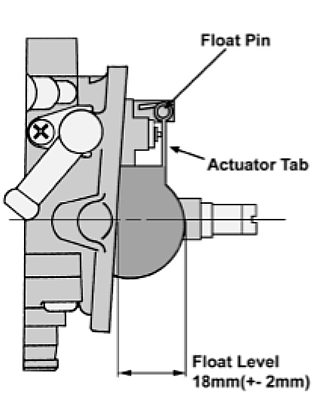
Float Level The float level can be checked and adjusted as per the diagram below. The measurement is best taken with the carb in a horizontal position, with the actuator tab just touching the needle.
Engine Block Breather Hoses
Various makes and models have different setups for engine block breather hoses. On the early Volvo models this consisted only of a hose that went from the breather on the driver side of the block and then went under the car. Later models were more complicated, with some having at least one hose that went to the carb air filter. The K& N air filters we offer with the Mikunis have fittings on the back for these hoses. ( Some of our early chrome top air filters did not.)
Mikuni HSR Tuning Instructions
Initial Tuning
The baci process of tuning these carbs is similar to that used to tune other carbs and some methods applied to SU's can be applied directly to the Mikunis, but there are significant differeneces The most significant differences are:
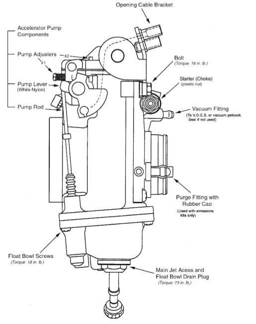
1) the Mikunis have an adjustable accelerator pump with start - stop adustable limit screws.
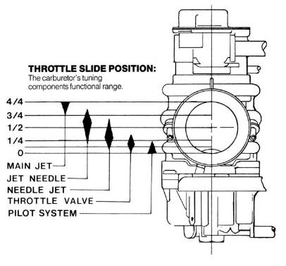
2) they are designed to be tuned in segments based on speed and throttle opening.
3) they have easily replaceable jets for low speed ( the pilot jet ), mid range ( the needle jet ), high speed - wide throttle opening- operation ( the main jet), and acceleration ( the accelerator pump jet ) as well as a jet needle that can be easily raised and lowered.
First make sure that your linkage is adjusted so that both throttle slides begin to open at the same time. Then make sure that they will open all the way when the throttle pedal is pushed to the floor. Next is the initial setup of the accelerator pump mechanism.
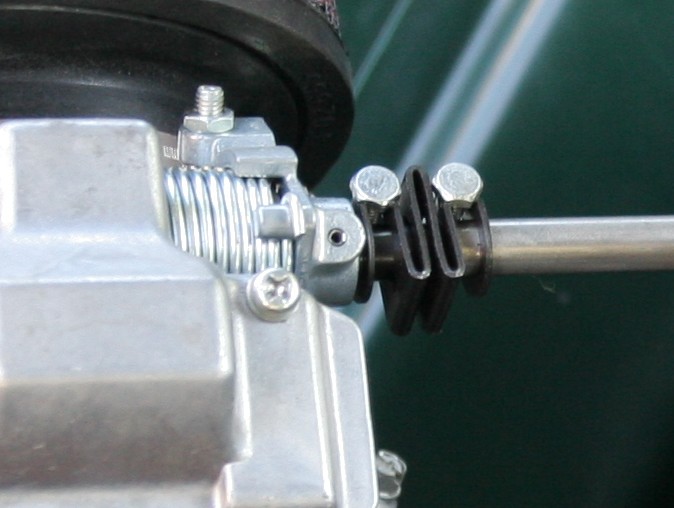
Accerelartor Pump First check to be sure that the accelerator pumps on both carbs begin to operate at the same time. Suggested initial adjustment is to have the pumps start to work as soon as the throttle slide starts to open. The two screws in the photo below set the limits of the cam that operates the accelerator pump plunger - setting the start point with screw #1 and stop point with screw # 2 for the accelerator pump in relation ot throttle slide movement. As tuning progresses the point at which the pump starts to operate is usually backed off so that it starts later. Screw # 2 is the main control for the amount of fuel pumped as it controls the length of the pump stroke.Back off the screw for a longer/larger shot of fuel.
.png)
Jet Needle Adjustment
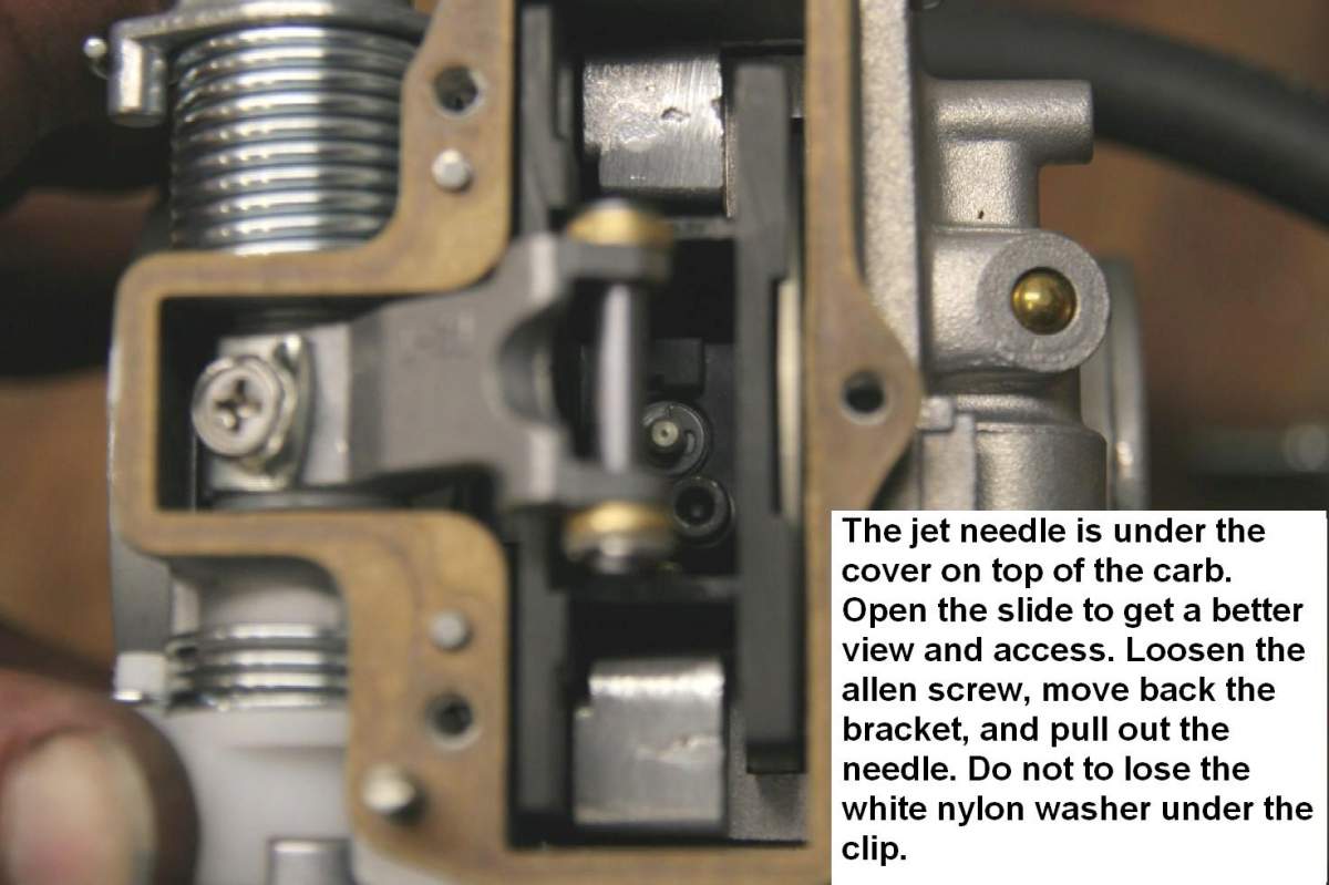
In many applications operation has improved with the jet needle raised by lowering the position of the clip at least one notch. If you are getting hesitation under acceleration, and your ignition timing and main jet are in the right range, than raising the jet needle is usually the first adjustment to make. To do this, open the top cover - 3 philips head screws. You might find it easier to open the throttle so that the allen head screw holding the needle in place is exposed. You will need a 2.5 mm allen wrench to loosen the screw clamping the needle in place. Use one with a long shaft as it makes the process much easier. Just loosen the screw, do not remove it. Slide the clamp plate to one side and grab the top of the needle with a pair of long nosed pliers. Do not lose the small white washer that goes under the needle clip. Once you have pulled the needle out, remove the clip from the center notch on the needle ( being careful that it does not fly away ) and lower it one or two notches to richen the midrange mixture. Press it back in place and reinstall the needle. You may find it easier to do this with the throttle open. Be sure that you do not loose the clip and the white washer that goes under the needle clip.
The photo above shows the needle clip one step down from the stock position - raising the needle.
 |
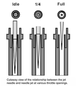 |
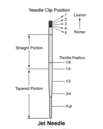
These carbs are specifically designed to fascilitate tuning by degree of throttle opening. The above diagrams show the affect of the shape of the jet needle in relation to the needle jet at various throttle openings. Leaner or richer needles differ mainly in the diameter of the straight portion of the needle and thus only have an effect at less that 1/4 throttle. We normally do not change jet needles and instead change to richer needle jets. Changing to a richer or leaner needle jet, located above the main jet, will have an affect at all throttle openings, though it is used mainly for mid range tuning.
Idle speed and mixture adjustments
Initial start up and adjustment of the idle speed and idle mixture is done as on most other carbs. This will also affect your off idle performance as the throttle is opened.
Idle Speed Adjustment - The idle speed adjustment screw is the long flexible shaft ( unless you have opted for replacement short idle speed screws ). It screws in (clockwise ) to raise the throttle slide and out ( counter clockwise ) to lower the throttle slide. The starting setting should be slightly raised from the lowest position.
Idle and Low Speed Mixture Adjustement - There are two tunable components in the idle system - the pilot air screw and the pilot jet.The pilot jet controls the amount of fuel and the pilot air screw controls the amount of air.
Pilot air screw - Turning the screw in ( clockwise ) will richen the mixture, and out ( counterclockwise ) will lean out the mixture. The pilot air screw is normally set at two turns out - check to see that both are still in this position.
Pilot fuel jet - The stock pilot jet is usually a 25 and is too rich for most automotive applications. We usually go at least one step leaner with a 22.5 jet which is the right size for most of our applications, so further idle and low throttle opening tuning is done with the pilot air screw.
Adjustment Procedure - Start the engine and bring it up to operating temperature. You may have to turn the idle speed screws ( the same amount on each carb ) to set a steady idle speed. With the engine at idle speed adjust the pilot air screw in until the engine speed decreases or the running becomes irregular, then adjust the air screw out until the engine speed increases and then decreases and/or the running becomes irregular. Count the number of turns between the two positions where the speed decreases and set the screw half way in between. So if the speed decreases at 1 turn out, inceases as the screw is turned out unitl the speed decreases at 4 turns out - set the screw at 2.5 turns out. If the idle speed is now too high, adjust with the idle speed screws.
If the best idle speed is achieved with the pilot screw much less than one turn out then the pilot jet is too small ( too lean ) and should be replaced with a larger one. If the engine speed does not slow down after 3 turns out, then the pilot jet may be too large ( too rich ) and should be replaced with a smaller one. If the pilot jet is too rich you will get poor fuel mileage as most driving is done at low small throttle openings.
Remember to check your ignition timing and make sure that there is sufficient advance. The amount of timing advance will affect the idle speed mixture. When the timing is changed significantly, the mixture may have to be re-adjusted. Many issues thought to be related to carb tuning have been diagnosed as ignition problems.
.jpg)
Turn the pilot air screw clockwise to the richen the low speed mixture, counterclockwise to lean the mixture.
Main jet
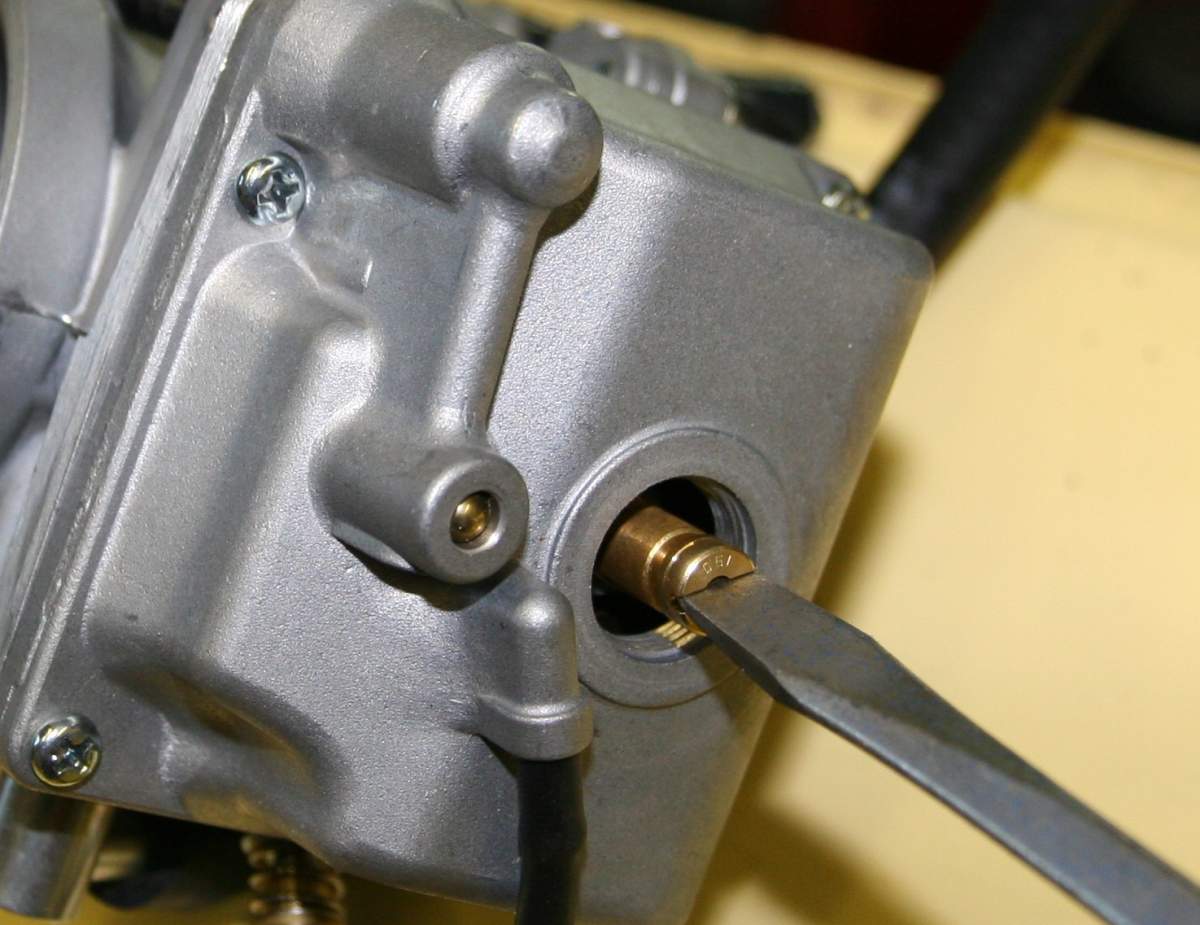
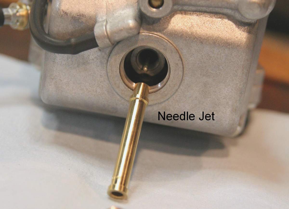
In most dual automotive applications ( except those at high altitude ), the 42 and 45 mm Mikunis have needed considerably larger main jets than the 160 ( 42 mm ) and 175 ( 45 mm) jets that originally come in the carbs. We usually end up with main jets in the 185 - 190 range. Kits shipped from mid 2009 on will have larger main jets included and usually already installed. Check the size of the main jet before installing the carbs. ( When wehave installed larger main jets the size is usually written on the float bowl.) The main jet is replaced by opening the large nut on the bottom of the float bowl, being careful to drain the fuel into a container if the carb is on the car. Then remove the small brass jet with a screwdriver as shown in the photo below. The main jet screws into the extender tube which threads into the carb body. This tube may come out with the main jet. The needle jet sits on top of, and is held in place by the extender tube and can drop out when the tube is removed. If it does, just slide it back in around the jet needle on reinstallation. It is sometimes easier to raise the throtle slide and jet needle when reinstalling. We normally have a selection of main jets in stock.
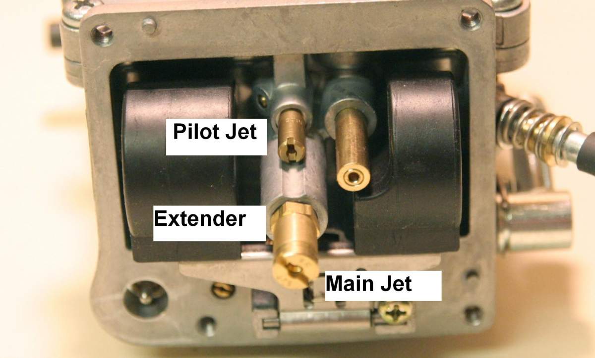
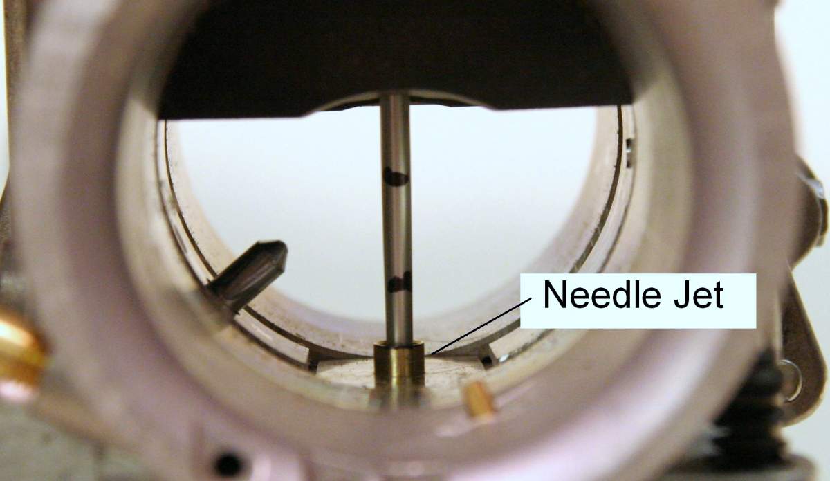
Needle Jet As Mentioned above, the Needle Jet is located above the Main Jet and Extender. It forms the opening around the Jet Needle. Installing a larger needle jet will richen the mixture throughout the throttle opening range controled by the needle and needle jet - mainly 1/4 to 3/4 throttle - the range most used in normal driving. Smaller jet needles are only smaller on the straight part of the shaft and so will only affect the mixture at small throttle openings. Installing a larger needle jet affects the whole needle range including the tapered area that is critical for a proper mixture during acceleration. The stock needle jet is a Y -6. The next richest is the Y-8. The richest is the Z -0. We routinely install either a Y - 6 or Z-0 for most applications. The photo to the left below shows the jet needle marked to show the relation of various locations on the tapered section of the needle to the top of the needle jet at various throttle openings.
 |
 |
Further Tuning
You should now be able to drive the car in a normal manner. If there is hesitation when coming on the throttle try raising the jet needle another notch or going richer on the main jet. Since most acceleration is done with the throttle more than half open, its the main jet that is going to have the most affect. During highway cruising the throttle is usually less than half way open, so the pilot jet and jet needle adjustment are the primary areas of concern.
For fine tuning the HSR tuning manual will help - http://www.mikuni.com/pdf/hsr_tuningmanual_021003.pdf.
In order to do accurate tuning you will have to have some method for determining whether the engine is running lean, rich, or just right in a particular operating range. You can use the traditional method of reading the spark plugs, or use the trial and error method where you tune richer and richer as long as that improves performance, and if it does not, go leaner and leaner as long as the results are positive - being careful to avoid backfiring or overheating due to an overly lean mixture. A considerably better way is to install an oxygen sensor and air fuel ratio gauge - and for extended tuning of a modified engine where top performance is important, put the car on a chassis dyno with an air/fuel ratio readout, and do most of the tuning there.
So in a typical dyno run with O2 sensor the engine is at low rpm and then you hit the throttle, opening it all the way and getting a shot of fuel from the accelerator pumps. It initially goes a little lean, shown in your air fuel ratio chart, as the sudden opening of the throttle slows down the air velocity through the carbs ( which decreases the vacuum that draws the fuel through - thus the need of for the AP ), then it flattens out. With the throttle plate all the way open your O2 sensor reading is from the main jet - and around 12 - 1 is in the proper range for max power under acceleration, but this varies from engine to engine depending on a number of other factors. The only way to find out whether going leaner or richer on the main jet will give you more power is to try it and see the result. We know that going leaner will give you better fuel mileage, but will it negatively affect the power ?
Now if you want to know whether you are too rich at part throttle cruise - which would be affected by the pilot jet and pilot air screw setting - then you have to do a steady state dyno run. Just enough load to be able to hold rpm steady with about 1/4 to 1/3 rd throttle opening. Or go out to a road where you can cruise steadily at part throttle - 1/4 - 1/3rd open, for a few minutes, then do a hot shutoff - cut the ignition and close the throttle and coast to a stop. Then check the plugs. The color will tell you whether you are too rich or too lean under cruise/part throttle conditions.
Another way to check it is too keep going leaner until you get some hesitation under acceleration and then go back a step.
A key to fine tuning these carbs is understanding the jet needle and needle jet and how they affect the mixture at various throttle openings and interact with pilot and main jet choices. There are also options to change the needle profiles, both in stock needles from Mikuni and on a custom basis, but these are usually not required. Start with adjusting the pilot air screw and changing the pilot jet if necessary, then move on to the jet needle and needle jet, then the main jet.
As with any other carbs used in multiple units, it is important that they be sychronized. The throttle slides must open at the same time and the same amount. The basic method for a dual carb setup would be to back off both of the idle speed set screws all the way, loosen the linkage between the carbs, allowing the throttle slides to equalize at full closed, and then tighten the linkage. Next would be to check that when the throttle pedal is pushed toward WOT that both slides are open equally when they are at the top of the carb opening.
A further method of equalizing the slides is to open the top of the carb, loosen the screw that holds the slide arm to the shaft, and re-tighten with the slides in the same position on all of the carbs.
 |
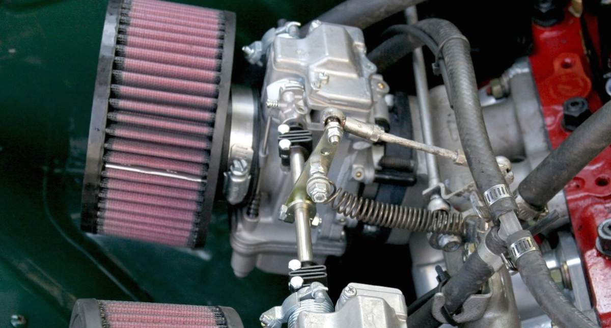
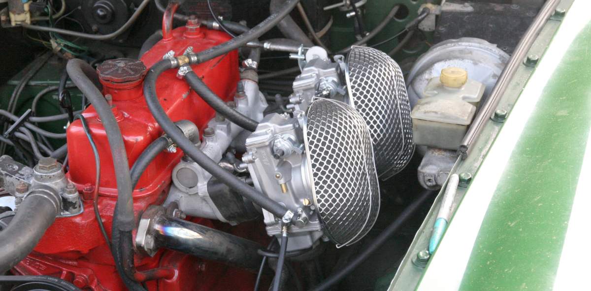
Air Filters There are several options for air filters. The standard filters are the rubber or chrome topped K & N filters with 3" fitler elements shown in photos above. There are other versions of these filters available where there is not enough room for the standard filters, including filters with 2" elements and offset mounts. Where room for the filters is especially tight there are special options available. See the photo below of the filters used in an installation on a 1979 MGB that was converted from single to dual carbs. It uses our adapter collars to allow other types of bolt on air filters to be used with modifications. The adapter collars fits over the mouth of the carb and the filter bolts to the adapter. They can also be used in air box installations and to install stock filters.
Please refer to the www.mikuni.com website, and their exploded views and tuning manual for
additional information. If you need further information or still have questions call or email us.